Welded Masonry Support

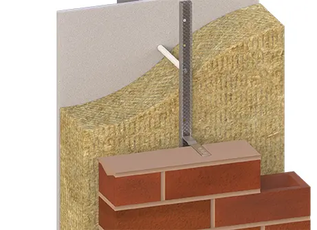
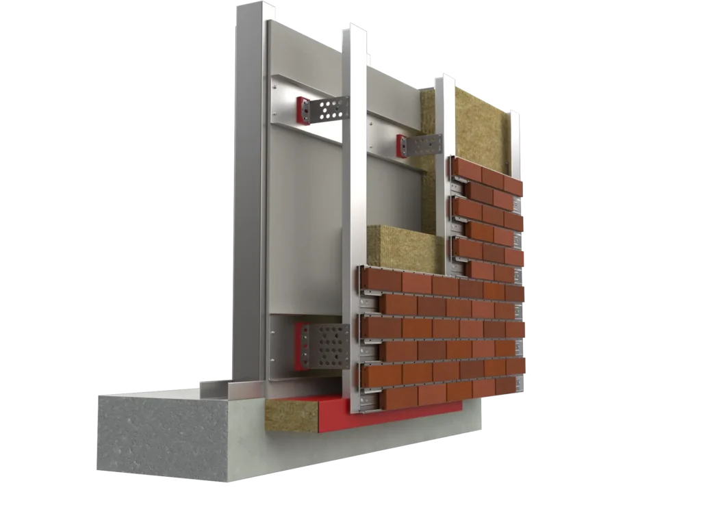
The welded system is ACS’s most widely specified masonry support, a continuous shelf angle with welded brackets suited to cavities of 50mm and above.

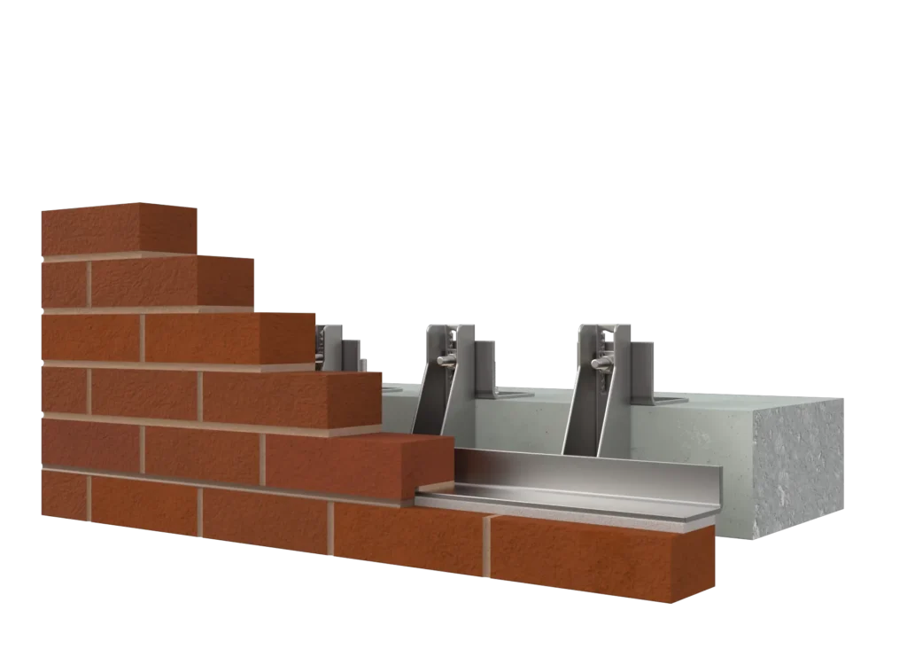
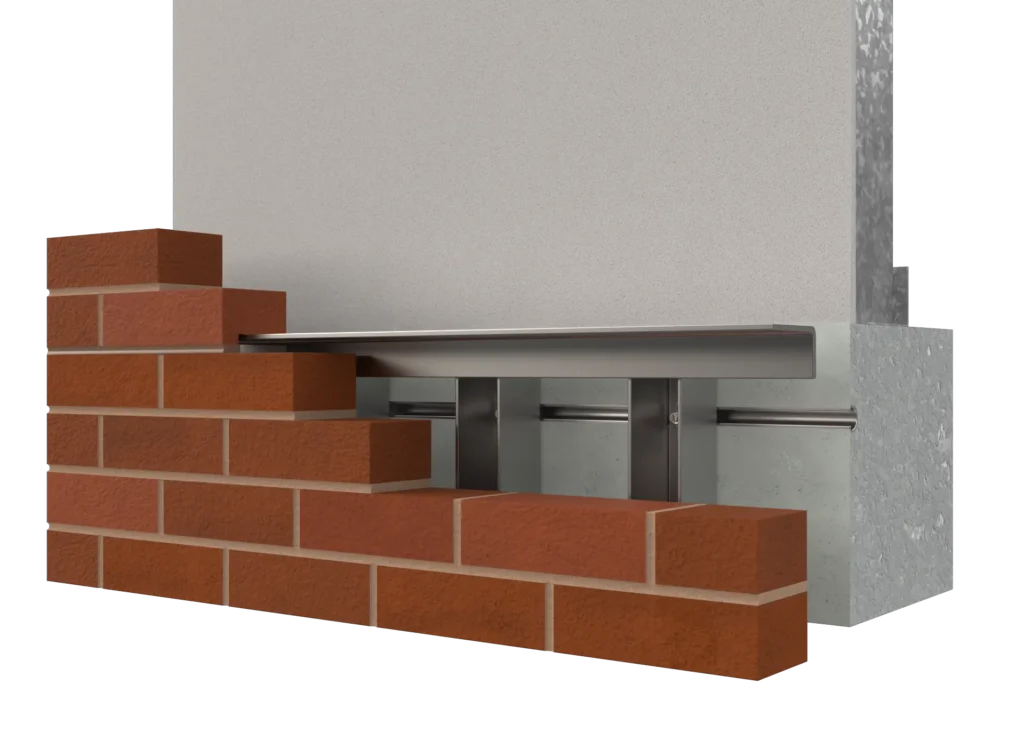
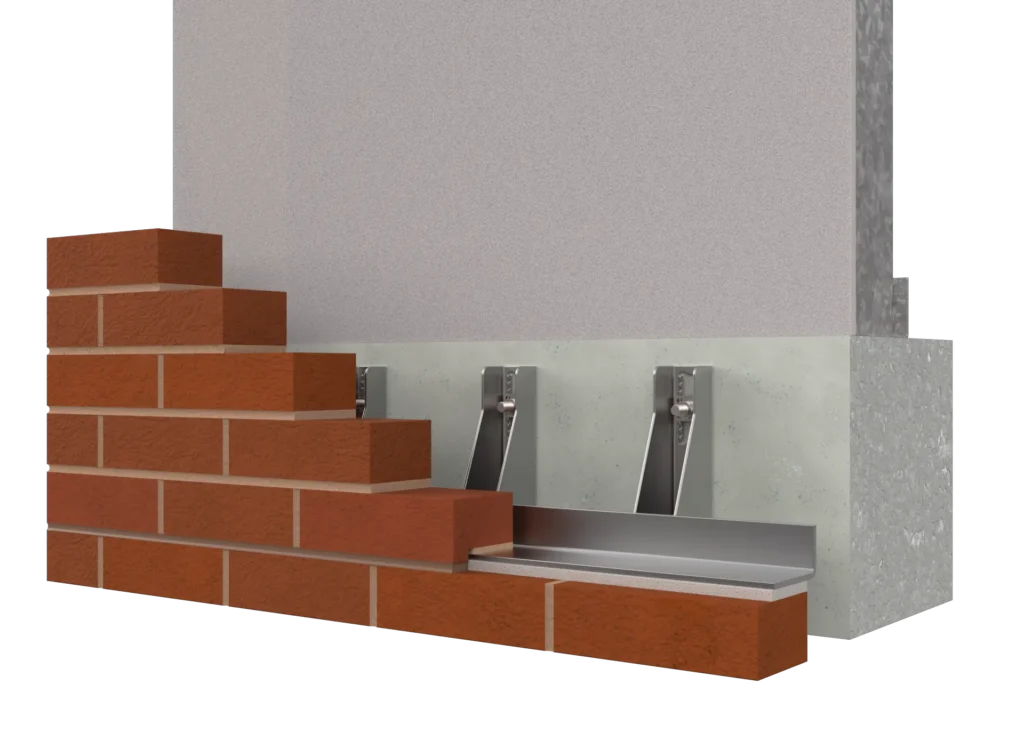
Masonry Support Fixed Back to Concrete

Masonry Support Fixed Back to Concrete

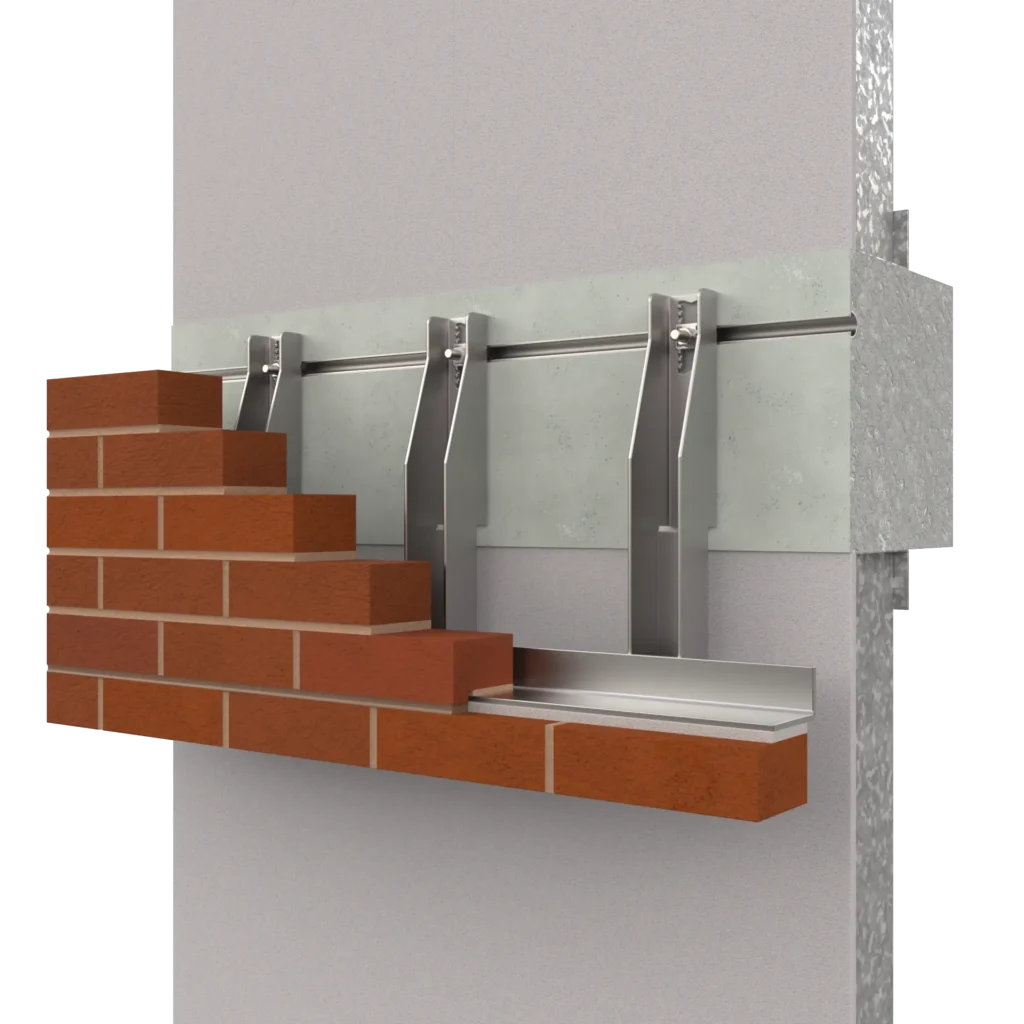
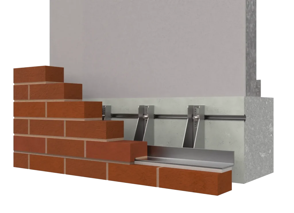
Masonry Support Fixed Back to Cast-In Channel

Masonry Support Fixed Back to Cast-In Channel

Fixed Back to Concrete & Cast-In Channel

Fixed Back to Concrete
Bolts directly to a concrete structure via expansion or chemical fixings. One of the most commonly specified configurations across residential, commercial and high-rise. Three-axis adjustment via Alpha II vertical adjustment, horizontal gap between angle lengths and stainless steel or thermal shims for cavity width.

Fixed Back to Cast-In Channel
Fixed back to ACS 31/21 AXIS cast-in channel via T-head bolts. The preferred configuration for continuous horizontal adjustment along the channel, with faster on-site installation and no on-site drilling into the structure.

Blue ACS logo

Want to learn more about our Masonry Support Systems?

Specifying welded masonry support? Engage our Technical Engineering Team early in the design process, and we’ll work alongside your design team to confirm the most efficient configuration, complete the calculations and provide the fabrication drawings and NBS specification details your project requires.

Get in touch

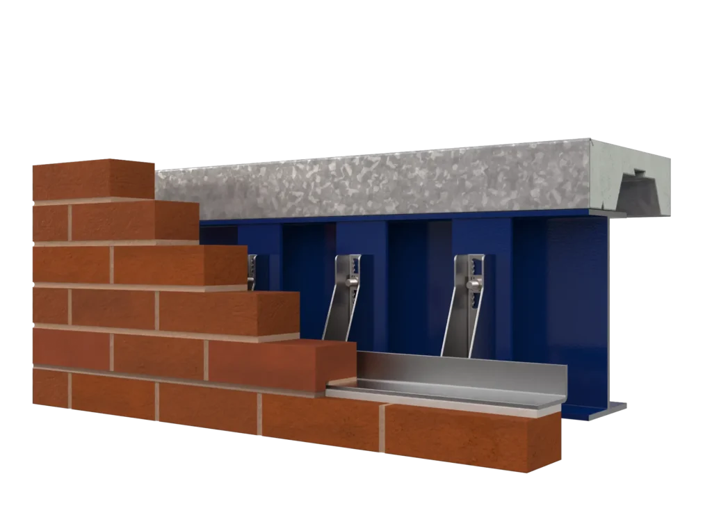
Masonry Support Fixed Back to Steel UB

Masonry Support Fixed Back to Steel UB

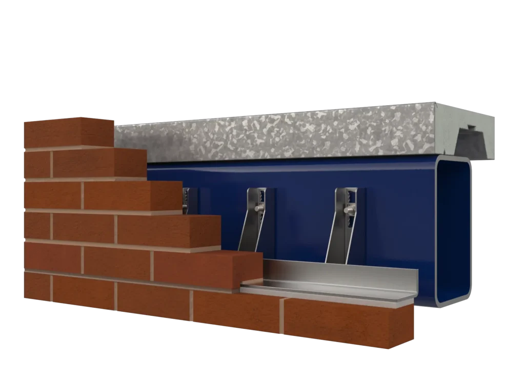
Masonry Support Fixed Back to RHS

Masonry Support Fixed Back to RHS

Fixed Back to Structural Steel

Fixed Back to Steel UB
Bolts to universal beams via welded plates or tees using hex head setscrews. The standard configuration for steel frame construction. Where dissimilar metals are in contact, we recommend isolation gaskets between bracket and beam and top hat washers between fixing bolt and drilled hole – both available from ACS.

Fixed Back to RHS
Bolts to the face of rolled hollow sections via blind bolts. Particularly suited to steel frame structures where access behind the fixing face is restricted. Same shelf angle and bracket assembly as our other configurations, with fixing engineered for limited access fixings. Where dissimilar metals are in contact, we recommend isolation gaskets between bracket and RHS and top hat washers between fixing bolt and drilled hole – both available from ACS.

Alternative Configurations

Fixed Back to Concrete Top Cleats
Hex head sets screws bolt the bracket assembly back to cleats fixed to the top of concrete slabs via expansion bolts or chemical fixings. Specified where face drilling to the structure isn’t possible – including party wall locations.

Inverted Masonry Support
Same shelf angle and bracket assembly with the angle located above the fixing points. Specified where architectural detailing requires the masonry to be supported from above rather than below – typically at pier and window-reveal details. Integrated reveal support available as a single fabricated component.

Masonry Support Fixed Back to Concrete Top Cleats

Masonry Support Fixed Back to Concrete Top Cleats

Inverted Masonry Support

Inverted Masonry Support

Projected Masonry Support

Projected Masonry Support

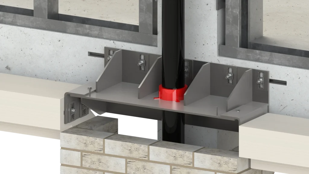
Masonry Support Special Example - Contact us for details

Masonry Support Special Example - Contact us for details

Bespoke and Specialist Solutions

Projected Masonry Support
Bracket assembly that drops the shelf angle down to window head level, supporting the masonry directly over the opening and removing the need for a separate lintel. Particularly useful where spandrel panel heights are small and there isn’t room for a conventional lintel-and-support arrangement – projection length, bracket geometry and fixing arrangement engineered to your detail.

Masonry Support Specials
Designed and manufactured in-house by our Technical Engineering Team, bespoke systems engineered to solve the most unique and architecturally challenging details, where standard configurations won’t do.
More Than a Manufacturer. A Compliance Partner.

Every ACS customer benefits from ACS Assured – our framework built on three pillars: Compliance Through Expertise, Assurance Through Transparency, and Performance & Innovation. From Gateway 2 documentation to full product traceability and sustainable manufacturing credentials, it’s built into everything we supply.

Award ribbon and check mark icon representing compliance
Compliance Through Expertise
Balance scales icon representing assurance
Assurance Through Transparency
Light bulb and gear icon representing innovation
Performance & Innovation

Masonry Support Specials and Bespoke Design

When the standard range can’t accommodate the demands of a project due to high loadings, unusual geometry, cavity constraints or complex movement requirements, our in-house structural engineers design fully bespoke masonry support systems engineered for the specific detail. Share your drawings and loadings with our Technical Engineering Team and we’ll develop a solution to meet the demands of your detail.

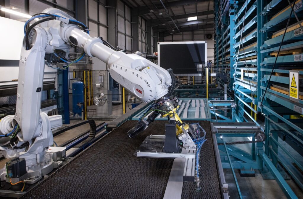
Industrial robotic arm on a factory production line
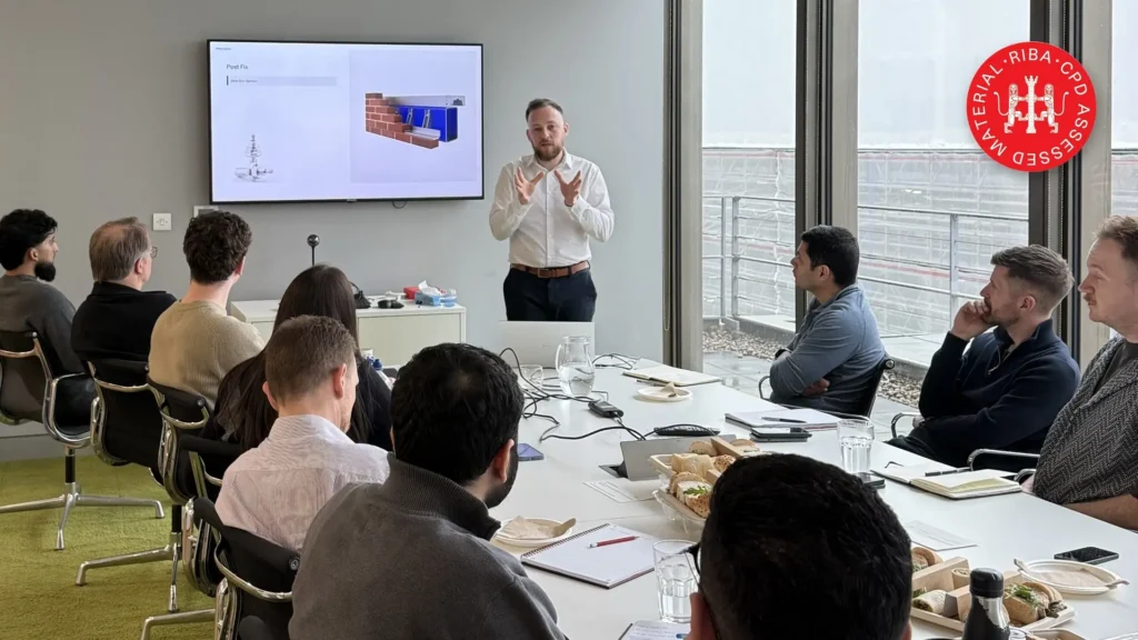
Presenter delivering an ACS CPD session to a seated audience, with the RIBA CPD assessed material mark

Masonry Support CPD

ACS runs a RIBA-accredited CPD on masonry support systems covering when to specify bracket and angle vs continuous angle, fixing configurations across concrete, steel and cast-in channel substrates, cavity and movement detailing. Available online or in person. Book your place, or get in touch to arrange a session for your team.

Tested, Certified, Trusted

Our bracket and angle, and continuous angle masonry support systems are independently tested and certified to UKCA, CE and CE+UKNI marking, fabricated to BS EN 1090, and CCPI certified for clear, accurate product information.

CCPI assessed product information mark for ACS masonry support
UKCA, CE and UKNI conformity marks
Download NBS/BIM

Access the NBS specification and BIM resources for this product to support your project planning, specification and design.

Request the CAD file

Need the CAD file for this product? Submit a request using our form and our team will be in touch.

Key Specification Details

  • Continuous shelf angle and welded bracket assembly for cavities of 50mm and above
  • Alpha II patented vertical adjustment system – fine adjustment up to +/- 25mm with positive locking teeth for load capacity greater than traditional serrated systems
  • Horizontal adjustment via continuous channel length (cast-in channel configuration) or 10mm design gap between angle lengths
  • Cavity width adjustment via stainless steel shims up to 12mm; thermal shims available (thermal conductivity ≤ 0.27 W/mK)
  • Manufactured from Grade 304 stainless steel as standard; Grade 316 available for coastal and higher corrosion environments
  • Minimum masonry bearing of 2/3rds
  • A1 non-combustible stainless steel – classified without testing in accordance with document 96/603/EC
  • UKCA / CE / CE+UKNI marked; designed and fabricated to BS EN 1090
  • CCPI certified
  • Delivered to site within 10 working days of final drawing and commercial approval

Technical Data Sheet

The ACS Masonry Support Technical Data Sheet covers structural tolerances, system types, movement joint requirements, wall tie positioning, bi-metallic corrosion guidance, thermal conductivity, A1 non-combustibility and full CCPI-certified specification information.

FAQs

When should I specify continuous angle instead of bracket and angle?
Continuous angle is suited to cavities under 50mm, where there isn’t depth to accommodate a bracket assembly. At borderline cavities, our Technical Engineering Team will work alongside your design team to identify the most economical specification for your project.
Three: fixed back to concrete via expansion or chemical fixings, fixed back to the ACS 31/21 AXIS cast-in channel via T-head bolts, and fixed back to steel via welded plates or tees. On new builds we’ll recommend the cast-in channel configuration where possible.
Isolation gaskets and top hat washers prevent contact between dissimilar metals at steel connections – both available from ACS as part of the system.
Grade 304 austenitic stainless steel as standard, with Grade 316 available for coastal or higher corrosion environments. Both are A1 non-combustible, classified without testing in accordance with document 96/603/EC.

Related Products

Need further information or technical support?
Our team can help.